
Waste Water treatment solution
We at Blue berry International control system provide ultimate solution and Engineering solution for Waste / Sewage Water treatment, Pumping Station, Raw water treatment and many more.
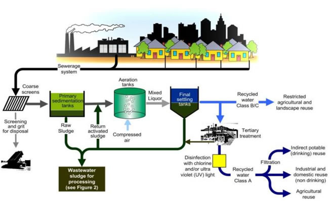
Water treatment process
Coagulation
Coagulation removes dirt and other particles suspended in water. Alum and other chemicals are added to water to form tiny sticky particles called "floc" which attract the dirt particles. The combined weight of the dirt and the alum (floc) become heavy enough to sink to the bottom during sedimentation.
Sedimentation
The heavy particles settle to the bottom and the clear water moves to filtration.
Filtration
The water passes through filters, some made of layers of sand, gravel, and charcoal that help remove even smaller particles.
Disinfection
A small amount of chlorine is added or some other disinfection method is used to kill any bacteria or microorganisms that may be in the water.
Storage. Water is placed in a closed tank or reservoir in order for disinfection to take place. The water then flows through pipes to homes and businesses in the community.
Semi-Auto Control Mode for Sewage treatment plant:
In this mode the RWPS will be operated automatically through the PLC based on certain inputs from SCADA system operator. The control philosophy is as below:
i) Pumps Start Routine: - the pump automatic / semi-automatic mode start routine will be as follows:
• Based on demand of water and level in raw water sump, the operator would enter the number of pumps to be operated and number of stand by pumps.
• Selects the combination of working & standby pumps.
ii) Any of the raw water pumps selected as working pumps will be started provided that the respective pump’s start permissive is available to the PLC, however PLC programming is done to avoid simultaneous starting of more than one pumps. The start permissive signal for each pump is available to the PLC only when the following safety interlocks are satisfied:
• Intake sump level is not low.
• Respective Motor Winding/ bearing temperature is not very high
• Respective discharge butterfly valves are available for operation and in close position.
• Respective pump thrust bearing temperature is not high.
• Emergency push button on the MCC is not operated
• Drive available input from respective pump’s switch gear panel (Which represents No power failure at starter/No drive fault, Breaker On)
• Supply Voltage is in good condition
Only if all the above interlock conditions are satisfied, then the pumps start immediately after the start sequence (as described below) is completed.
In addition to above start permissive interlocks, the following critical interlocks are also checked for tripping of pumps during running condition:
• Motor protection (overload trip)
• Dry run protection through level switch
• Emergency stop circuitry.
• Motor winding temperature very high
• Protection against pipeline burst. (By sensing the pressure)
If any of the above stated interlocks become unhealthy during the running of the VT pumps, the PLC or the hardwired interlocks will immediately trip the respective VT pump. As soon as the pump trips, the trip status is annunciated on the alarm annunciator provided on the SCADA PLC Panel in the control room.
iii) Start Sequence:
• Start Command will be issued to pump & the speed feedback is observed in the PLC
• After preset pressure is developed in the pumping main, Open command is issued to the discharge butterfly valve (Valve operating time for full opening shall be 15 to 120 sec.)
• If duty pump fails to start or its discharge valve fails to open, the discharge valve is closed and the pump start command is withdrawn. Start sequence will be initiated for the next Duty pump.
• If the duty pump starts & its discharge valve are fully opened within the preset time delay of 150 sec, the start sequence for the pump is completed.
The pumps will keep running until low level is reached or duty cycle is changed. In any condition, no two pumps will be started simultaneously.
A software based “pump start sequence failed alarm” will be indicated on the SCADA screen, if a start sequence fails to complete within a set time. In case of tripping of any of the working pump the next duty pump or standby pump as per logic will be started. After the duty cycle of the selected combination is over at the end of 48 hours (time duration adjustable), an alarm will be generated on the SCADA system, prompting the operator to either Start the Standby pump or continues with the same combination of pumps.
iv) Stop Sequence – The stop sequence can be initiated by operator by pressing stop push button on the SCADA for the respective pump or it is automatically initiated by the PLC on actuation of any of the safety interlocks:
• Close command is issued to the respective discharge butterfly valve.
• After a preset time delay (adjustable), stop command is issued to pump drive.
• When the pump stops and the discharge valve is fully closed, the stop sequence is completed.
• A software based alarm for “pump stop sequence failed” will be generated on the SCADA screen, if stop sequence fails to complete within a preset time.
• If the pump stops under hardwired trip condition, the discharge valve will be closed by the PLC. In case power supply to the motorized valve is not available the valve is closed by PLC on resumption of power.
Auto Mode of Pumping station:
The auto mode will be similar to the semi auto mode except the duty cycle will be rotated automatically by the PLC system.
The raw water VT pumps will be automatically duty rotated so as to achieve equal running hours of all the VT pumps. For this purpose, there will be a duty cycle of combination of pump duties as working and standby. These combinations will be rotated (cyclically) automatically at the end of 48 hours (time span adjustable); for example when a specific combination completes its duty cycle the next standby pumps will be in operation.
• In case a working pump fails the standby pump will start automatically prompting an alarm to the operator.
• Facilities will be provided for selecting the combinations of pumps operations manually by the operator in the SCADA screen.
• Time counters are be provided in the PLC system, for registering the run time for each pump.